2015年7月31日星期五

The air filter installation should pay attention to what matters?

The air filter installation should pay attention to what matters?

(1) The working pressure must not exceed the maximum pressure indicated by the filter.
(2) filters are generally installed after the after cooler and the gas tank, as close as possible to the point of use, and the lowest temperature point.
(3) The filter should be installed after the quick opening valve and prevent reflux and impact of the phenomenon.
(4) The filter should be mounted vertically, with sufficient space to replace the filter at the bottom.
(5) the larger filter in the pipeline should be properly supported.


Extensive use of the air compressor

Years ago, it was common for shops to have a central power source that drove all the tools through a system of belts, wheels and drive shafts. The power was routed around the work space by mechanical means. While the belts and shafts may be gone, many shops still use a mechanical system to move power around the shop. It's based on the energy stored in air that's under pressure, and the heart of the system is the air compressor. 

You'll find air compressors used in a wide range of situations—from corner gas stations to major manufacturing plants. And, more and more, air compressors are finding their way into home workshops, basements and garages. Models sized to handle every job, from inflating pool toys to powering tools such as nail guns, sanders, drills, impact wrenches, staplers and spray guns are now available through local home centers, tool dealers and mail-order catalogs. 

The big advantage of air power is that each tool doesn't need its own bulky motor. Instead, a single motor on the compressor converts the electrical energy into kinetic energy. This makes for light, compact, easy-to-handle tools that run quietly and have fewer parts that wear out.

How to choose the air compressor control system?

How to choose the air compressor control system?

The purpose of any air compressor control system are the most efficient way to match the demand and supply of compressed air. The vintage electric pneumatic control being based on the upgrade software of the control of the microprocessor and to be able to optimize the system and control parameters are replaced, but any type of control is a constant speed control or shift control.
Fixed speed compressor control
Name suggests, this method is to let the air compressor speed is constant, the specific speed is determined by the drive function of the transmission ratio of the motor speed and the transmission apparatus, the transmission means can be a gear or triangular belt port and the gas supply amount control based on the modulation control or poppet valve control .


Modulation control
This form of control is adjusted based on the exhaust pressure of the air compressor to the intake valve of the air compressor. When the controller detects that the exhaust pressure increases, it starts to close the intake valve. Although this control is effective, but the efficiency is the lowest. The reason is that an efficiency is inversely proportional to the pressure ratio of the air compressor, the ratio of compression ratio, i.e. the exhaust gas pressure and the intake pressure. The closure of the intake valve at the inlet of the air compressor to generate a vacuum, and the exhaust pressure is relatively constant, this is equivalent to the increased pressure ratio.
Remedial measures is limited modulation control adjustment range Once the output drops to less than about 40%, 60% on the automatic control program into the load / no-load control. Unfortunately, this control can not be applied to multiple machines.
Variable row and Control of
Can change the air compressor displacement control the effective length of the rotor. Mainly on the host plus cone or spiral valves, control the internal bypass. Although the efficiency of such control is better than the modulation control, but the helical valve control in more than 50% to 60% capacity, and this control debugging complex and difficult.
Unload / load control
Such control is simple and effective, the use of fully closing the intake valve when the pressure reaches the upper limit (disconnected) in the compressor discharge pressure at the switch, and to fully open the intake valve when the pressure reaches the lower limit (access). The modulation control difference is that this control air compressor implement internal unload. Pressure ratio decline leads to wasted effort and consumption decline. This type of control can take advantage of the the sequencer (main) controller to easily connect multiple air compressor equipment. On the other hand, the air system will need to install a suitably sized air storage tank.
On / off control
This is the most effective control program. The air compressor is either running at full load or outage, depending on the signal at the mouth of the pressure switch, unfortunately, more than 10hp motor accordance with the requirements of this control often start and off will cause overheating. This control commonly used in small piston compressor installation of storage. This differential pressure of the air compressor is relatively large, up to 15psig to 25 psig.
Variable speed control
The technology of the advanced economies to the air compressor application variable frequency drive technology. The principle sounds simple, precise control air compressor / motor speed according to system requirements. If properly designed, variable frequency control is fine-tuning of the most advanced and energy saving air compressor control port, however, some of the following questions must be given to solve.
Air Compressor host to be designed into the host has a higher efficiency throughout the rev range port efficiency is a function of the speed of the rotor tip line, may be too low or too high speed dropped significantly.
Variable speed drive controller as an additional coupling between the power supply and the drive motor, and must be sufficiently efficient. Mechanical and electrical performance must not drive systems and electric power distortions and the effects of electromagnetic radiation, in order to avoid the computer or other sensitive electronic equipment from electromagnetic interference. The drive motor must handle high speed image processing as efficient low speed, high speed bearing design and cooling problems may be more trouble. Intelligent controller to establish a highly efficient and reliable link between the air pressure, motor and air compressor inlet valve. A well-designed device can accurately control the compressor discharge pressure within 1 Psi And despite the gas fluctuation range. The variable speed control to adjust the compressor running, it allows sequencer / controller in the efficient running parallel air compressor mouth run at full capacity according to the demand part of the air compressor, the rest of the air compressor in the aside standby mouth variable speed control can effectively compensate for the volatility of gas demand.
Yet even the most efficient control system can not compensate for the improper design. A comprehensive system of checks to the air system, so that the control system has the opportunity to achieve efficiency.

Energy-saving principle of frequency conversion air compressor

Energy-saving principle of frequency conversion air compressor


In recent years, with the continuous improvement of the global energy prices, energy-saving products more and more attention of the industrial enterprises. Air compressor as a power-hungry industrial enterprises, its economy running more and more importance in enterprises. Frequency conversion to adjust the air compressor has been widely welcomed its excellent operating efficiency in industrial enterprises.
The vast majority of the use conditions, there is great fluctuation of the user of the compressed air demand. Traditional air compressor by adjusting the air compressor inlet valve to regulate the flow of the air compressor, the air compressor gas production and the user's actual demand balance. This adjustment regulation is inefficient, leading to a lot of wasted energy. Frequency conversion air compressor by adjusting the frequency of the power to regulate the speed of the compressor motor, thereby regulating the speed of the air compressor host so the actual output of the air compressor gas and customer's actual gas consumption to reach consensus. The flow regulator can avoid a lot of wasted energy in the inlet flow rate adjustment method is the most efficient air compressor flow regulation on the market. The principle of frequency conversion air compressor system as shown below, currently on the market, all series of frequency conversion air compressors are based on the principles of design and manufacturing.
Inverter air compressor to deliver benefits
Inverter air compressor to subvert traditional air compressor operation control, has brought many benefits to the customer.
1 low start-up current: adjustable motor speed, the inverter compressor starts gradually accelerate from low speed, low starting power, the starting current is small, smooth start, no impact on the power grid, the unit can be use in the area of ​​grid capacity is relatively low.
Occasions, the use of energy saving / Save money: there is a change in the user gas consumption
Frequency conversion unit, to the maximum extent possible to avoid crew uninstall run there is no waste of electricity, the energy saving effect is obvious. The entire life cycle of the air compressor, compared with the conventional non-inverter air compressor, the average frequency conversion air compressor can save about 35% of electricity, equivalent to 22% of the total cost of air compressor.
Pressure stability: the rotational speed of the motor can be precisely controlled, fast response speed varies with the pressure, so the air compressor of the exhaust gas pressure fluctuation is small, the user can be used in more stable and lower pressure subzonally units; the same time, the user can configure a smaller gas tank to further cost savings.
Other issues related to frequency conversion air compressor
Frequency conversion air compressor Although there are many benefits, but also a lot of information has also repeatedly raised, but here was to make the following two pay attention, to avoid air compressor user to enter some misunderstanding.
An inverter air compressor particularly applicable to larger changes in gas consumption occasions, if the user changes in the gas consumption is very small, the gas is very stable, the use of the energy saving effect of the frequency of the air compressor is not very obvious. The energy saving effect is good or bad inverter air compressor and gas mode.
Frequency range of inverter air compressor and gas adjustment range is limited, not necessarily the bigger the better. The reason is that only a small range of efficient air compressor host speed zone, the greater the range of variable frequency adjust its edge to leave the host efficient speed zone farther, the lower the efficiency of the host. In addition, on the motor will have the same problem, so the overall efficiency of the units in the lower speed will be significantly reduced. In general, the frequency conversion air compressor frequency control range of 40-100% is the most valuable

The ventilation problem resolution of the air compressor system

The ventilation problem resolution of the air compressor system

Air compressor overheating problems often encountered here to talk about why screw air compressor overheated Several factors appear:
Environmental factors often ventilation conditions have a great impact on, air compressor surrounding environment affect the main factors of the heat following three phenomena: the distance from air compressor placed too close to walls or other obstructions; There is compressed air near the unit may have to other sources of heat, In this regard, it is recommended that strict environmental requirements in accordance with the installation and use of the air compressor, air compressor installation and use.
The radiator plugging also appear. Because long-running radiator appearance adhesion layer of dust or sludge may be, it will make when the air compressor ambient dusty, it will affect the cooling effect. The oil filter is dirty also may lead to overheating of the air compressor to a certain extent. Because the air compressor oil filter thus making due to dirty oil, normal traffic can not enter the air compressor, it will allow the air compressor to rapid warming due to insufficient cooling lubricants. Of course, there is the cooling oily surface low. This proposal should regularly service and maintenance of air compressor, to avoid the occurrence of the above.
If there will be oil label or oily corresponding problems, air compressor should use the original manufacturers dedicated air compressor oil, such as the use of other low-grade or low-grade oil may make back viscosity and specific heat cause overheating and other problems not up to standard.
As a reminder: the air compressor should use original spare parts and maintenance package, because its must be tried and tested to achieve certain technical requirements, counterfeit goods and alternatives can not achieve. Only use original spare parts in order to ensure the stability and reliability of the air compressor running, once interrupted, will be a serious threat to the normal operation of the air compressor, thereby affecting the user's production schedule, production quality and operating efficiency.

Leaking oil-free air compressor filler components analysis

Leaking oil-free air compressor filler components analysis


Oil-free air compressor gas seal components leaking common phenomenon: 
the outside of the housing of the air seal, bolts along a fixed gas seal leakage or seepage;
along the trolley leaking or dripping inside the gas seal seepage both cases.
1, leaks or drops in the gas seal assembly outside the housing along the fixed gas sealing bolt infiltration caused by reasons of external leakage of the gas seal assembly housing is due to the aging of the O-ring of the lower end of the gas seal assembly. Caused Mifengbuyan, so that the cooling water leakage. Then if oil scraper ring damage or Mifengbuyan of the, it is possible to make the cooling water along Rod inflow sump, resulting in oil emulsification, and in severe cases can cause the crankshaft locking bush-burning and other accidents. Commonly used to replace the appropriate O-ring work to solve this kind of problem.
In addition, the cylinder block casting defect is caused by one of the reasons for leaking gas seal components outside of the housing. Cylinder aging or due to the casting, the cylinder breakage, cracks or trachoma, can also cause leakage of oil-free air compressor gas seal components outside of the housing.
Deal with these problems, a concrete analysis of specific treatment, usually welding to repair or replace the cylinder. Repaired cylinder hydrostatic test must be carried out to ensure the safety of the cylinder.
2 caused the internal components of the gas seal along the trolley muddy water or drops of seepage along the compressor the trolley running water or drops of infiltration, when severe leakage of the internal components of the gas seal leakage not more common, but the reason is more complicated, mainly as follows: when, if coupled with damage to the oil scraper ring, cooling water is likely to enter the sump internal, caused by the serious consequences of the same as described above. The common cause of the following aspects:
Aging of the upper end of the assembly housing 
(1) a gas seal with the cylinder connected at the mat or mat thinner causing Mifengbuyan, so that the cooling water into the internal cylinder. This phenomenon in the piston down, the most obvious. When dealing with this type of problem, the commonly used method is to replace the gasket. Replacement cushions, it is best to use the depth gauge measured the size of the top of the cylinder gas seal assembly housing, according to the measured data to determine the increase in the right mat, if necessary, can also be coated with a layer of polymer sealant to increase the sealing effect.
(2) cylinder bed damaged or Mifengbuyan the the one of the reasons is also caused by leaking gas seal assembly. When the cylinder bed damaged or the cylinder head bolts are not tightened in accordance with the provisions of torque, and will cause cylinder leaking. In the piston during operation, cooling water may be the direction of the piston rod into the gas sealing, causing leakage. We should pay more attention to this problem, if the severe water cylinder bed, may cause the piston cylinder, even to appear top cylinder vicious accident. The method of dealing with such problems is to replace the cylinder bed or torque required to re-tighten the cylinder head bolts.
(3) gas seal assembly housing can also cause damage, blisters, cracks, leaking gas seal assembly. As the gas seal assembly housing in contact with the cooling water for a long time, in the oil-free air compressor work, cooling water temperature is high: when the compressor does not work, the water temperature is low, this water temperature alternately changing phenomenon easily compressor air seal assembly housing have a scale, severe appear the phenomenon of cavitation, resulting in the casing perforations. In particular, some casting defects such as trachoma, stomatal weak places, the most prone to breakage, cracking or perforation, may cause leakage of cooling water. Causing oil emulsification, to cause crankshaft strain, bush-burning and other accidents. Deal with such issues is timely repair or replacement of the air seal assembly housing.
Leaking oil-free air compressor filler components, though not common, but if the event tend to give oil-free air compressors have serious consequences. Especially for oil-free air compressor disrepair due to aging equipment, air sealing components most prone to water leakage, therefore, carry out regular inspections of these oil-free air compressors, and would be prepared for, it is very necessary.

How to control the noise pollution of the silent oilless air compressor

How to control the noise pollution of the silent oilless air compressor


Air compressor noise control muffler, muffler trenches and sound insulation technology three aspects:
1, the installation of air compressor muffler:
The major source of noise is the intake and exhaust ports, should use the appropriate intake and exhaust muffler. Compressor intake noise spectrum was the low frequency characteristics of the intake muffler should be used in the resistant structure, or a resistance-dominated impedance composite structure. The exhaust gas pressure of the air compressor, air velocity, should be used in air compressor exhaust port holes muffler.
2, set the air compressor muffler trenches:
Muffler trenches of underground or semi-underground tunnel, tunnel wall into a good acoustic properties of brick. The air compressor intake manifold and muffler the trenches connected, so that the air entering the air compressor through the muffler tunnel. The muffler Hang air compressor intake noise can be greatly reduced, the service life is longer than normal muffler.
3 acoustic enclosures:
In the intake and exhaust ports of the air compressor is installed muffler or after setting silencer trenches, flow noise can be reduced to below 80dB (a), but the mechanical noise of the air compressor and motor noise is still high, so should pneumatic acoustic enclosures installed on the machine unit. 4 hanging space absorber: air compressor station of one of our customers, a tall empty plant reverb heavy. In plant roof dispersed suspension the absorber plant noise can be reduced 3-10db (a), the reverberation time is reduced by 5-10s.

Air compressor fill oil method

Air compressor fill oil method


In the operating state, the oil level of the compressor should be maintained between the minimum and maximum oil level, the oil and more will affect the separation effect, less oil will affect the machine lubrication and cooling performance,  if the oil level is below the minimumThe oil level should replenish lubricants, is:
1 downtime internal pressure release is completed (confirmation system without pressure), pull down the main power switch.
② Open the fuel filler on the oil and gas separation tank, add the right amount of cooling lubricants.

How to clean the air compressor cooler

How to clean the air compressor cooler

Each air compressor run around 2000h clear cooling surface dust, cap the cooler fan bracket purge hole open to be purged of the cooler air gun blowing dust until the cooling surface dust purged. Still serious heat surface dirt is difficult to purge and clean, remove the cooler, pour the oil cooler and four import and export closed to prevent dirt from entering, and then both sides with compressed air blowing dust or water rinse, final drying surface water stains. Back into place.
Remember! Do not scrape the dirt with a wire brush, and other hard objects, so as not to damage the radiator surface.
Condensate
The moisture in the air may condense in the oil and gas separation tank, particularly in wet weather, when the exhaust temperature is below the dew point pressure of the air or shutdown cooling, there will be more condensed water precipitated. The oil contains too much water will cause lubricating oil emulsion, affect the safe operation of the machine, such as:
1. Causing compressor Host poor lubrication
2. Oil and gas separation effects of variation, the larger oil and gas separator differential pressure
3. Cause mechanical rusting.
Therefore, should be formulated based on humidity conditions the condensate drain timetable.
Condensate discharge method
Should shut down the machine, oil separator tank pressure sufficiently cooled condensate fully precipitate, such as the morning before starting.
(1) screwed out of the bottom of the oil separator tank ball valve screw plug.
(2) Slowly open the ball valve drain, close the valve until the oil outflow.
(3) screw on the ball valve screw plug.

Air compressor how to care for and maintain

Air compressor how to care for and maintain

Air compressor to run normally reliable guarantee of the life of the unit, it should be to develop a detailed maintenance plan, fixed-man operation is performed, regular maintenance, periodic inspection and maintenance, the air compressor group kept clean, no oil, no dirt.
Note:
A. The above table when the maintenance and replacement of the various components must be determined: the pressure within the air compressor systems have been released, have been separated with the other pressure source, and the switch on the main circuit has been disconnected and is ready permitted closing the security identification .
B. The replacement time of the cooling lubricant of the compressor depends on the use environment, whether the pH of gas humidity, dust and air. New air compressor purchase the first 500 hours of operation shall be replaced with new oil every 4000 hours, after normal drain intervals replaced once annual run of less than 4,000 hours machines should be replaced once a year.
C. Oil filter in the first boot run 300-500 hours must be replaced, the second replacement, and later at the normal time to replace every 2000 hours to 2000 hours.
D. Remember when the repair and replacement of the air filter or intake valve to prevent any debris falling into the compressor host cavity. Host entrance closed operation, after the operation is completed, by hand several revolutions host the direction of rotation, no obstacles to boot.
E. Machines each running about 2000 hours required to check the tightness of the belt, if the belt is partial loose, need to be adjusted until the belt tensioner; belt scrapped due to oil pollution in order to protect the belt, the need to prevent the whole process.
F. Every oil change, oil filter should be replaced at the same time.
G. Replacement parts to maximize the use of part of the original company, or a matching problem, the vendor will not be responsible.

three basic types of air compressors


The three basic types of air compressors are

The three basic types of air compressors are
1.    reciprocating.
2.    rotary screw.
3.    rotary centrifugal.
These types are further specified by:
1.    the number of compression stages.
2.    cooling method (air, water, oil).
3.    drive method (motor, engine, steam, other).
4.    lubrication (oil, Oil-Free where Oil Free means no lubricating oil contacts the compressed air).
5.    packaged or custom-built.
Reciprocating Air Compressors
Reciprocating air compressors are positive displacement machines, meaning that they increase the pressure of the air by reducing its volume. This means they are taking in successive volumes of air which is confined within a closed space and elevating this air to a higher pressure. The reciprocating air compressor accomplishes this by a piston within a cylinder as the compressing and displacing element.

Ventilation fans Mounting

Ventilation fans

Ventilation fans  Type
  axial
  centrifugal
  tangential
  mixed-flow
  semi-centrifugal


Ventilation fans  Functions
  ventilation
  cooling
  transfer
  exhaust
  aspirating
  extraction
  warming
  drying
  joining
  fume exhaust
  circulation
  wall


Ventilation fans  Air flow

Other characteristics
  blades angled towards the back
  high-pressure
  EC motor
  medium-pressure
  double-inlet
  belt-driven
  blades angled towards the front
  single-inlet
  high-performance
  with external rotor
  mobile
  direct-drive
  low-pressure
  AC
  DC
  with airfoil blades
  high-flow
  open-blade
  energy-efficient
  with adjustable blades
  high-temperature
  wide temperature range


Ventilation fans  Materials
  metal
  plastic
  composite


Ventilation fans Options and accessories
  compact
  explosion-proof
  throw
  watertight
  energy-saving
  low-noise
  low-speed
  modular
  high-volume
  conical
  soundproof
  large-diameter
  low-noise


Ventilation fans  Mounting
  wall-mount
  ceiling
  in-line
  floor standing
 

Ventilation fans applications
  for air ducts
  for roof
  for heating
  blower
  for pipe
  heat exchanger
  for tunnels
  for fireplaces
  window
  refrigerator
  plug
  cabinet


Ventilation fans  Domains
  industrial
  commercial
  laboratory
  for indoor use
  for aeronautics
  for military applications
 

propeller blades or fan blades criteria

Industrial Fan Blades, Axial Fan Blades, or Propellers


There are typically four criteria used in the design of propeller blades or fan blades.
  1. The material it is made from.
  2. The number of blades.
  3. The blade shape.
  4. The blade pitch angle.
Material:
The material used in industrial propellers or fan blades is generally fabricated steel, cast or fabricated aluminum, fabricated stainless steel or other exotic metals. Plastic propellers have become common, but typically only in commercial or residential fans. Fiberglass is also available for corrosion or chemicals resistance.
Number of Blades:
The number of fan blades is generally only limited by the size (diameter) of the propeller.
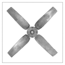
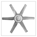
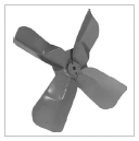
Props will generally have as few as 2 blades, up to 16 blades. Some even have an odd number of blades such as 3, 5 or 7. The most common are 4 and 6 blade props.
Blade Shape:
The shape of the fan blade can be almost anything from square to round to rectangular. The corners are typically always rounded for greater efficiency and less noise. In most cases, large square blades are used to obtain the highest volume with the lowest noise.
Blade Pitch Angle:
The blade pitch angle is a critical factor in the overall performance of the propeller.
In general, the greater the pitch angle, the slower the fan can turn. Some propellers or fan blades are made with adjustable blade pitch angles either set at the factory or adjustable while operating (in-flight adjustable).
Multi-piece Cast Aluminum Prop One piece Cast Aluminum Prop Steel or Stainless Steel Prop

What Is the Difference Between a Blower & a Fan?


What Is the Difference Between a Blower & a Fan?

If you're comparing air conditioners, furnaces, appliances or certain electronic devices, you'll likely see the labels "blowers" and "fans" used in the product descriptions. There is a distinct difference between blowers and fans, and knowing that difference can help you choose the best product for your needs.

Airflow

  • The "specific ratio" of a fan or blower is the ratio of discharge pressure over suction pressure. In other words, it correlates to the amount of air the device is able to move. Fans have a ratio of up to 1.11, while blowers have ratios between 1.11 and 1.20). In short, blowers create more airflow than fans.

Size

  • Blowers are typically bigger. While they move more air, blowers are impractical for certain smaller items or airflow systems. Standard propeller blades are rare for blowers, and the units often use a larger and more complex centrifugal device.

Energy Efficiency

  • Depending on the fan or blower manufacturer, energy efficiency varies. A fan, however, usually consumes less energy than a blower.

Blower vs. Fan

People use blowers and fans for many different types of situations. Blowers, also known as centrifugal fans, are in automobile systems and home heating, ventilating and air-conditioning (HVAC) systems. Fans, also known as axial fans, are in automobile cooling systems and home ventilation systems. A typical window box fan is an example of an axial fan. Both types have advantages and disadvantages.

Airflow

  • Axial fans force airflow along the axis of the rotating shaft, which spins the fan. In an airplane, the propeller forces the air from the front of the plane to the back along the sides of the plane. Centrifugal fans pull air in along the axis, but forces it out perpendicular to the axis. If you look at a blower from a car's HVAC system, then you will see that the blower takes air in through the front and sends it out along the sides of the blower.

Power

  • Axial fans tend to require more power than centrifugal fans. Because these fans are designed for low-pressure, high-volume situations, they require more power to achieve the high rotational speed necessary for normal operation. When you need high efficiency, use centrifugal fans. Centrifugal fans can generate high pressures, but in a more efficient manner than axial fans. For this reason, centrifugal fans are the most used type of industrial fan.

Flexibility

  • Despite the advantages of a centrifugal fan over a axial fan, axial fans do have some disadvantages. The most important is stall speed. A centrifugal fan alone cannot maintain a constant airflow over a varying flow rate. Another issue with centrifugal fans is maintenance. Because of the positioning of the motor and the fan, it can be difficult or impossible to perform maintenance on the motor without removing the fan unit. This can be very time-consuming.

Noise

  • If you compare the amount of air moved against the amount of noise the fan or blower makes, then you would find that blowers produce less noise than axial fans of the same size. The reason is the increase in fan speed. Since axial fans have to rotate at a higher speed than a similar-sized centrifugal fan, the axial fan will produce more noise.


Blower Motor Specifications

Blowers are equipment that increases the velocity of air. Blowers are used in a wide variety of applications from automobile heating and cooling systems to industrial process ventilation systems. Blowers typically consist of blades or vanes that spin at a high rate pulling in air from one side and expelling it at a high velocity on the discharge size. Each application requires specific air flow requirements that are driven by blower motor specifications.

Horsepower and Environment

  • The required air flow on the discharge of a blower is a function of the size and configuration of the blower fan blades as well as how fast the blades spin. The revolutions per minute of the blades are a function of the blower motor horsepower. Horsepower is a unit of energy that correlates electrical energy input to mechanical energy output. Some industrial applications require blower motors to operate in a hazardous or flammable atmosphere. Blow motor specifications for these applications require intrinsically safe motor designs to avoid ignition sources.
  • Horsepower is a unit of energy and an important motor specification.

Installation and Configuration

  • Blower motors contain a central rotating shaft that converts electrical energy into mechanical energy. The shafts can be coupled to the fan blades directly or have intermediate components such as gears or pulley belts. These components can increase or decrease the output force of the blower motor. Space requirements and installation are also an important specification as a blower motor must adequate and safe operating room as well as be protected from any dripping liquids or materials.


    Blower motors can be close coupled or belt driven.

Power Requirements

  • A blower motor must be specified for phase, voltage and direction of rotation. Alternating current has a sine wave characteristic with a peak and a valley for each cycle. Three phase voltage cancels out the peaks and valleys with opposite waves. Consistent power supply such as three phase voltage increases the efficiency of a blower motor. In addition, the voltage of the power source must be specified as 110, 220 or 440 volts. Since a blower operates by spinning fan blades, the direction of rotation is critical to either push or pull air. This must be specified before installation.


How to Calculate CFM From RPMs

How to Calculate CFM From RPMs


Developers of air-movement mechanisms such as fans and compressors must consider the basic relationship between fan or impeller speed in rpm (revolutions per minute) and volumetric air flow in CFM (cubic feet per minute). While these machines have different operating principles, their common characteristic is that each revolution of their spinning input shaft will result in a certain amount of volumetric air (or gas) flow through them when they are operating as designed according to their pitch or displacement factor.


Axial Ventilation Fans轴流通风机

  1. Define the axial fan application. According to the general fan law governing axial fans, you will need to know the fan blade diameter and pitch (blade tilt or attack angle) along with the rpm variable to calculate CFM. In this example, a small household fan on a stand has a three-bladed plastic fan with a 1-foot diameter and an 8-inch effective pitch. This means that each revolution of the running fan blows the one-foot-diameter column of air coming through the fan 8 inches toward you after accounting for efficiency losses. The fan is running at 1,200 rpm.


  2. Calculate the linear velocity of the air through the running fan. If each revolution moves the air 8 inches, then 1,200-revolutions per minute multiplied by 8 inches means the air 9,600 is being moved at inches per minute, or 800 feet in one minute. Another way of looking at it is that the fan is moving an 800-foot-long column of air that is 1 foot in diameter through space each minute.


  3. Calculate the CFM (volumetric flow of air) at 1,200 rpm. The volume of the column of air described in Step 2 is pi (3.1416) x fan radius squared (0.5-feet squared) times the column length in feet. This would be 3.1416 x 0.25 square feet x 800 feet = 628.32 cubic feet per minute at 1200 rpm.

Centrifugal Blower Fan (Squirrel Cage-Blower)

  1. Define the blower application. In this example, the centrifugal blower in a window air conditioner circulates 600 CFM on the "LO" setting when the blower motor is spinning at 800 rpm. You can calculate how much air would it circulate in "HI" mode, when the motor rotates at 1200 rpm.


  2. Define the terms in the general centrifugal fan formula and rearrange them to use the formula to solve for the higher air flow: CFM 1/CFM 2 = RPM 1/RPM 2 x (D1/D2)^3 (cubed). The (D1/D2)^3 is 1, since the impeller diameter stays the same, so CFM 2 = CFM 1 x (RPM 2/RPM 1).


  3. Substitute your parameters in the equation to calculate the higher airflow:
    CFM 2 = 600 CFM x 1200 rpm/800 rpm = 900 CFM

Reciprocating Compressor Applications

  1. Define the compressor application. A shop compressor with a piston in a cylinder has a net displacement of 10 cubic inches. It normally turns at 600 rpm. You can calculate many cubic feet of air it takes in at atmospheric pressure and the approximate cubic feet of compressed air it supplies if it has an overall 10-1 compression ratio.
  2. Calculate the incoming volumetric air flow. If the compressor takes in 10 cubic inches of air for each revolution, then CFM input = 600 RPM x 10 cubic inches/1728 cubic inches/cubic foot = 3.47 CFM.
  3. Calculate the outgoing compressed air volumetric flow. Since the compression ratio is 10-1, the compressed air would be supplied at 3.47/10, or 0.347 CFM.